Category Archives: Sem categoria

Final product

Final product

We have now completed coding so the system functions as required. Also the components are fully attached along with all the soldering. The wires have also been shortened so it reduces the mess and makes the board look a lot more organised. As for the final stage, we had to fit the breadboard and the Arduino into a box that is stylish and a decent size. Improvising in this section, we decided to use a clothes box which was the ideal size for our system. Before inserting the components, we had to cut the areas needed to display the LCD and the buttons. This had to be done with accurate measurements so that the areas are not cut too much or too less. An issue was faced once the components had been inserted into the box. The problem was that there was too much space inside the box causing the components to move around. This was a serious issue because the hardware is fragile so if its constantly being moved then it may be damaged. To overcome this problem, we decided to attach some foam inside the box.  This allowed the components to remain firmly in place and nothing was moving inside. This was now our final stage of the project and the product is fully developed and functioning correctly. Only thing left to do was to actually test the product with users.

Here are some pictures of the final product:

IMG_20141208_164412 IMG_20141208_164423 IMG_20141208_165314 IMG_20141208_170713

Coding

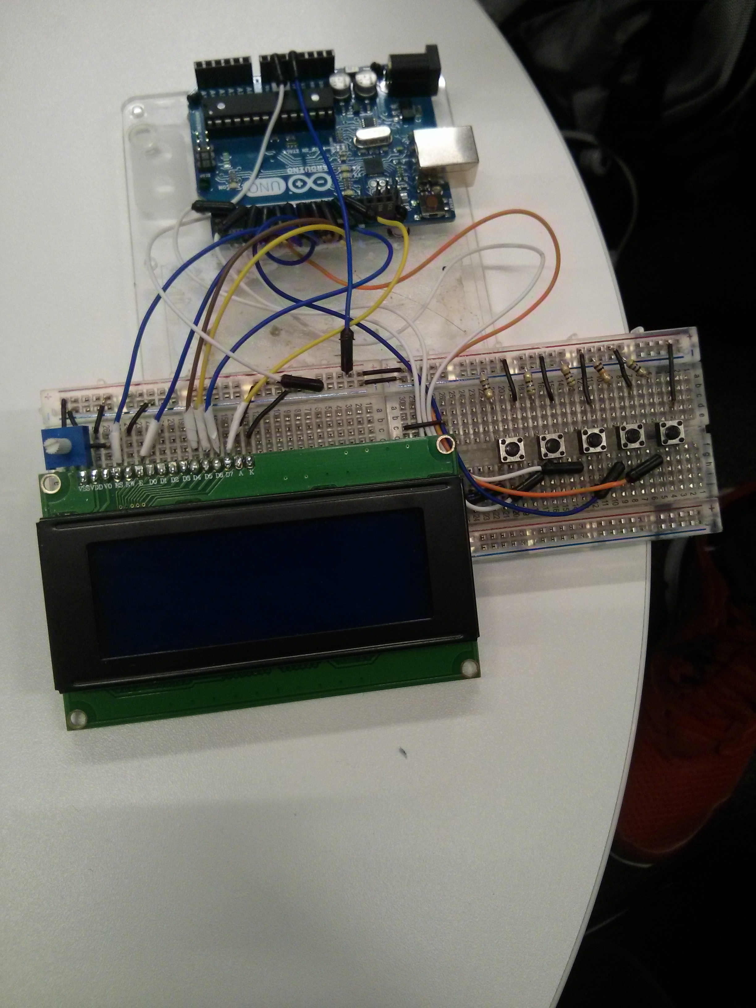
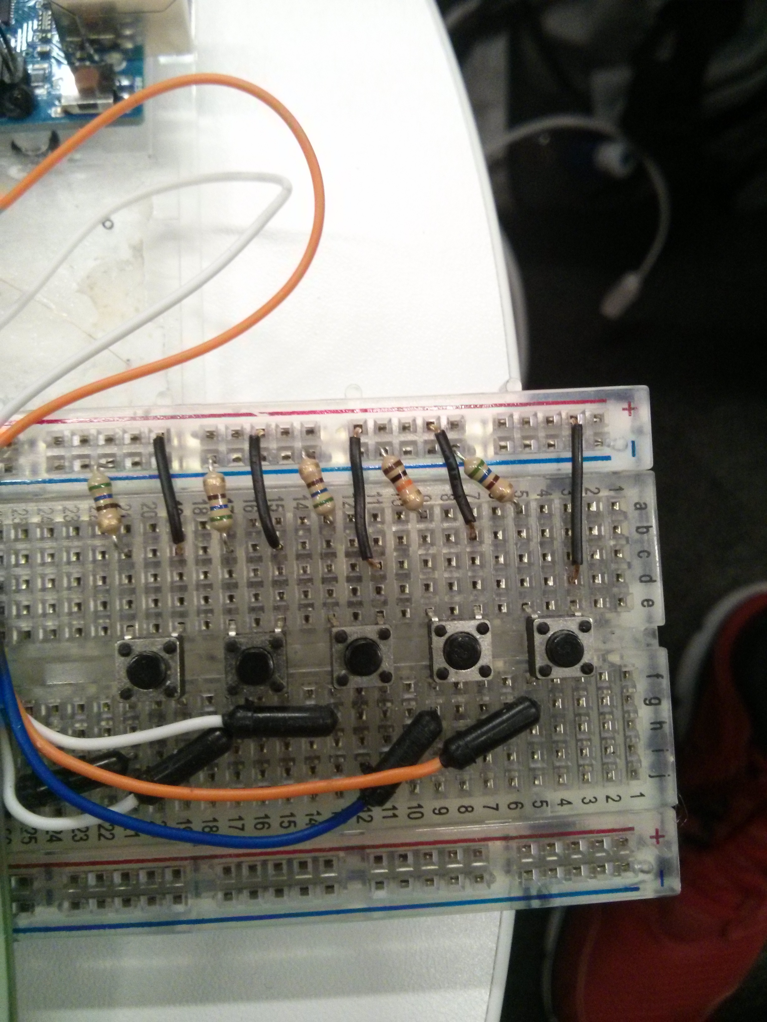
This post will include our code for the project. All the codes listed below are provided with full commenting making it very easy for someone to recreate our project. Along with the code, we have also provided the Fritzing diagram so anyone will have full instructions on how to wire all the hardware components as well as a clear understanding of the software.

Here is the code below:

// project.ino
#include <LiquidCrystal.h>
#include <string.h>

LiquidCrystal lcd(7, 8, 9, 10, 11, 12);//initialize the library with the number of the interface pins

//Select each interface pin for each button
const int button_up= 02;
const int button_down= 03;
const int button_left= 04;
const int button_right=05;
const int button_done= 06;
const int button_print=0;
//——————————————

//variables to read the button states
int state_up=0;
int state_down=0;
int state_left=0;
int state_right=0;
int state_done=0;
int state_print=0;
//———————————————

//string will all the letters from the alphabet
char alphabet[27]= {‘_’, ‘A’, ‘B’, ‘C’, ‘D’, ‘E’, ‘F’, ‘G’, ‘H’, ‘I’, ‘J’, ‘K’, ‘L’, ‘M’, ‘N’, ‘O’, ‘P’, ‘Q’, ‘R’, ‘S’, ‘T’, ‘U’, ‘V’, ‘X’, ‘W’, ‘Y’, ‘Z’};
//matrix that will store all the names
char name[20][17];

char password[]=”MASTER”;

int i;//counter for loops
int j=0;//count the order of each inserted name
int pos=0;//determines the position of the cursor in the name
int alpha=0;//runs the array alphabet
int RET=1;
void setup() {

Serial.begin(9600);
//define all the buttons as inputs
pinMode(button_up, INPUT);
pinMode(button_down, INPUT);
pinMode(button_left, INPUT);
pinMode(button_right, INPUT);
pinMode(button_done, INPUT);
pinMode(button_print, INPUT);
//———————————
lcd.begin(20, 4);//starts the lcd display, 20 rows 4 lines
for(int k=0; k<20; k++)//initiate all the names with ‘_’
for(int l=0; l<16; l++)
name[k][l]=’_’;

}

void loop() {

//read the state of each button
state_up=digitalRead(button_up);
state_down=digitalRead(button_down);
state_left=digitalRead(button_left);
state_right=digitalRead(button_right);
state_done=digitalRead(button_done);
state_print=digitalRead(button_print);

lcd.setCursor(0, 0);
lcd.print(“ENTER YOUR NAME:”);
//i=0;
//lcd.setCursor(i, 1);
//lcd.blink();

for(i=0; i<16; i++)//will update the lcd screen with the typed character
{

lcd.setCursor(i, 2);
lcd.print(name[j][i]);

}

if(state_up==HIGH)//when up is pressed, runs from a-z in a ascendent order
{
if(alpha==26)//if you are in the ‘Z’ character, goes back to the beggining
alpha=0;
else
alpha++;
name[j][pos]=alphabet[alpha];//insert the chosen character in the respective position

}

if(state_down==HIGH)//when down is pressed, does the same as above, but in a descendent order
{
if(alpha==0)
alpha=25;
else
alpha–;
name[j][pos]=alphabet[alpha];

}

if(state_left==HIGH)//move between characters in the display
{
if(pos==0)//if you are in the first character and press left, goes to the last character
pos=15;
else
pos–;
alpha=give_back(j, pos);

}

if(state_right==HIGH)//the same as above
{
if(pos==15)
pos=0;
else
pos++;
alpha=give_back(j, pos);

}

if(state_done==HIGH)//when done is pressed, save the name, and open the next position in the matrix for another name
{
pos++;
name[j][pos]=”;
RET=strcmp(name[j], password);
Serial.println(RET);
if(RET==0)
{
press_print();

}
else
{
RET=0;
pos=0;
j++;
alpha=0;
}

}

/*if(state_print==HIGH)
{

press_print();
}*/

lcd.setCursor(pos, 2);//blink the cursor in the position that can be changed
lcd.blink();
delay(150);
//lcd.clear();
//lcd.blink();

}
int give_back(int j, int pos)//returns the respective ‘number’ of the character when the cursor moves back to a position
{
int c=0;
while(name[j][pos]!=alphabet[c])
{
c++;

}

return (c);

}

void press_print()//print the list of names in the serial monitor
{

lcd.setCursor(0,3);
lcd.print(“Printing on Serial”);
delay(1000);
lcd.clear();
for(int w=0; w<20; w++)
{for(int y=0; y<16; y++)
Serial.print(name[w][y]);
Serial.println(“”);
}
j=0;
pos=0;
for(int k=0; k<20; k++)//RESET THE MATRIX AFTER PRINTING
for(int l=0; l<16; l++)
name[k][l]=’_’;

alpha=0;
//delay();

}

How is it connected? Fritzing diagrams

project breadboard

In the diagram above, it is possible to see how we wired our product. Here is a brief description of each connection:

LCD Display: composed by 16 pins, from 1 to 16 counting from left to right:

* Pin 1- connected to ground (it is responsible for the backlight)
* Pin 2- connected to 5V (it is responsible for the backlight)
* Pin 3- Connected to the potentiometer, so it is possible to change the brightness
* Pin 4- connected to Arduino pin 7 (tell the display if it is printing a data or a command byte)
* Pin 5- connected to ground since is not used, because we are just writing to the display
* Pin 6- connected to Arduino pin 8. This is the EN pin, tells the display if the data is ready for reading.
* Pin 7,8,9,10 are no used
* Pin 11,12, 13 & 14- connected to Arduino pins 9, 10, 11 & 12. These are the data Pins.
* Pin 15- connected to 5V, provides energy for the display
* Pin 16- connected to ground.

Reference: https://learn.adafruit.com/character-lcds/wiring-a-character-lcd

In our device we also have 5 buttons: Up, Down, Left, Right & OK. We used the pushbuttons that came in our kits and they are wired in the standard way. They are connected to the following pins:
* UP- Arduino Digital pin 2
* DOWN- Arduino Digital pin 3
* LEFT-Arduino Digital pin 4
* RIGHT- Arduino Digital pin 5
* OK- Arduino Digital pin 6

In a first attempt of building the device, we used the digital pin 1, and it turned up that the LCD display wasn’t working properly. After some research, we discovered that the digital pins 0 and 1 are for Serial reading.

Here is the electronic diagram on fritizing:
project schematic

Accessibility

We have now completed our project and achieved our goals however with time remaining until the deadline, we decided to add extra features that will improve the user experience by providing smoother interaction. Also we considered making our product user friendly and easily accessible for every individual including some with poor eye sight or lack of understanding.

First idea we came up with was to attach a feature which will give the user an option to adjust the brightness of the screen. This was an excellent idea as it will help someone with poor eye sight the chance to read with extra brightness. Also this feature will give user the power to control the contrast of the screen so they will be able to adjust to their preferences.

Implementation-

The perfect component to use for this feature was a potentiometer as this will ideal for user to control the contrast. Just like a light rotating switch in a room to control the power of the light, we will use the potentiometer to control the brightness of the screen. We have relative knowledge on how to function a potentiometer thanks to our previous lab work so we didn’t face any difficulty implementing this to our system. We simply connected the potentiometer to an available analog pin the attached it to the readings of the LCD screen. The image below shows a clear picture of the potentiometer switch.

Screenshot_2014-12-09-13-56-39

Week 4- Storing data and soldering

Week 4- Storing data and soldering

Continuing from previous tasks and the problems that we faced, we have now resolved these issues and our program is functioning correctly meeting all the conditions and objectives. Last week, we struggled to overcome the problem we faced which was to store the data after users input and also give admin the rights and permission to be able to print out list of names.

My partner William has come up with a solution to correct this. He has added an array of matrix and then declared a void storage of data which stores all the names of the users. The void print function then detects the encrypted password assigned to the administrator which only they will know. Once this password is inputted then the void print function will recognise and system will print out all the names stored in the matrix of array. William has also created a function that will reset the matrix once the list is printed. This will allow the admin to delete all unnecessary data as well as store relevant data for future evidence.

Soldering-

This registry system is now functioning successfully as the users are able to input their names which can then be viewed by the administrator at any time. In our case, this will record a collection of students attendance to the lecturers office. We now had to solder few wires to be held in position more firmly and also cut some wires short to keep all the cablings neat. The picture below shows how our final product looks with all components attached and wires connected.

IMG_20141208_164351 IMG_20141208_164356

Week 3

This week we have made a substantial amount of progress with our program. Our project is now functioning effectively and allows user to Input data. We have started implementing different methods of features to meet our program’s conditions. In this blog, we will discuss our current progression and our upcoming plans.

After successfully learning how to display message on our LCD, we were ready to implement more complicated codes to accomplish a registration system. The first stage was to wire all the cables and components needed for this project. For e.g setting up four buttons in the breadboard to be used as right, left, up and down arrow. We then started writing up the final codes. First action was to declare all the Variables including all ints for buttons and an array of strings to create an alphabetical list. We also assigned the digital pin to the buttons through the use of digital read.

Strings- This was to list all alphabets as variables including a space feature. User will be able to press up and down to select their alphabetical characters.

Array list- Used to store the alphabets in a collection of array. Also allowing user to store their names so later admin will have option to print the list of names.

If statements- This was for giving instructions to the buttons of how to respond if a button is pressed. For e.g is the button up is pressed then the condition will be to add value to the array of alphabets. This allows to go through different letters.

Additional features

Blink effect- This was a bonus feature to add to our program. The role of the blink effect is flashing constantly on the cursor position giving the user more visibility of which character they are at. This will also provide better experience for user by having more interaction and easy navigation.

IMG-20141127-WA0009

Next objectives.

Now that we are able to input users details, our next stage will be to store this data and give access to the administrator so that they will be able to print users list. Also we will look to shorten our cables so that we can fit it inside a stylish box making it a better presentation. Finally, if we get the chance to the create some more additional features for improving users experience.

Test 1- Displaying message

We have now received all the required components to complete this project. We will now begin implementation process of coding the program and connection of components. The first thing we had to do was to solder the required pins on the LCD display so that it is attachable to the breadboard. This had to be done very carefully because the soldering machine melts the metal very fast so we had to make sure no to spread the melted metal preventing it from damaging the board.

The next stage was to wire all the cables allowing the LCD display to be fully connected to the Arduino. We used 16 by 4 so it was important to make sure that additional wires are connected. We have also inputted a potentiometer so it allows user to control the contrast of the LCD. This feature was implemented after considering user accessibility as some users may need extra brightness to view the message on board. Now that all wires are connected and the board is live, we had to write up the code to test the board.

The liquidCrystal library was imported and hello world code was used to understand the basic of displaying a message. We then did some research on adding more effects and customizing the font style. After learning new methods, we were able to add features like blink effect so the curser is constantly blinking and setting manual curser so the characters are spaced out and using different lines. This test has been successful because we now understand how to effectively display numerous messages with customized features. Here are pictures below that demonstrates our progression. I have also linked a video clip which illustrates the LCD in action.

IMG-20141126-WA0005

IMG-20141126-WA0004

Video link: https://www.youtube.com/watch?v=lK_Z06EZYL0

The Idea

The invention of LCD display using Arduino has inspired us to develop our project. LCD display feature is used very commonly in today’s era. This is very beneficial to our society as it provides important information to the general public. The LCD display is also used for artistic work  and this is demonstrated in different land marks around London. During different seasonal holidays in London, LCD displays are used for decoration to set the seasonal theme. We may not realise but LCD display technology are designed in most of the services we use today such as train schedules, road signs and building closing times. Although understanding the importance of LCD display, we noticed that in most services it is only used as one way communication which only provides data to users however we wanted to innovate on this idea and develop something that will provide 2 way communication allowing user to have more interaction.

platform-display LCD used for train information

This has given us the idea to develop an LCD that allows a user to input information which can be stored and return output as confirmation. This can be beneficial for many public services but our focus is on education. Our LCD board will be designed to allow a student to store their record of presence. If they went to visit a lecturer and his not there then they will be able to input their name to keep a record of their visit or leave a message for the lecturer. For us to successfully create this display board, we will need a selection of Arduino components and increase our knowledge on using different methods in programming such as Arrays and variables.

We will update our work via blogs to notify our progress.